Connections
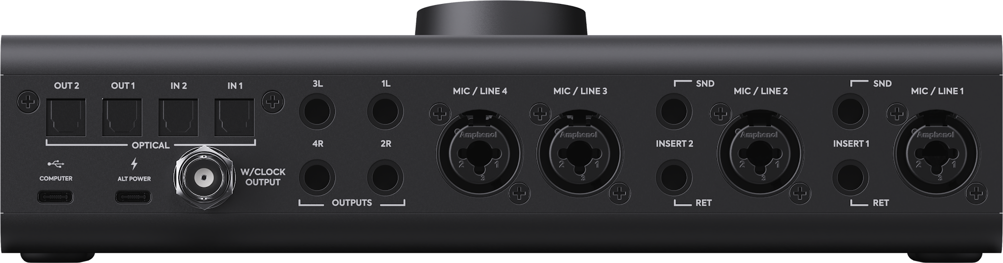
USB-C Computer Connection
The USB-C COMPUTER connection carries audio and control data between iD4+ and the host computer. It can also supply bus power when the host USB-C port provides 5 V / 3 A (15 W). Connect directly to the computer using a USB-C to USB-C cable for bus-powered operation.

ALT POWER
A second USB-C port labelled ALT POWER is provided for power only. It does not carry audio or control data.
The ALT POWER port requires an external 5 V / 3 A (15 W) USB-C power source connected with a USB-C to USB-C cable. A USB-A to USB-C cable cannot be used for external power, regardless of the power adaptor's current rating. Connect external power whenever the host USB-C port cannot supply 3 A, or whenever using a USB hub. When ALT POWER is connected, iD4+ automatically switches from bus power to external power. Keep the COMPUTER port connected for audio and control data; with external power connected, a USB-A to USB-C cable can be used for this data connection.

Monitor Outputs
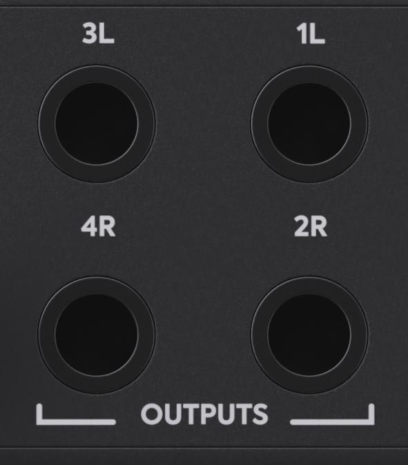
Four balanced TRS line outputs provide the Main and ALT monitor connections.
Outputs 1–2 are the Main monitor output and Outputs 3–4 are the ALT monitor output. Connect the left and right speakers of your Main pair to Outputs 1 and 2 respectively. If using a second pair, connect them to ALT Outputs 3 and 4.
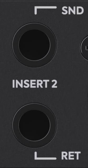
Balanced Hardware Inserts
iD4+ provides two balanced hardware inserts on analogue Inputs 1 and 2. Each insert uses separate balanced TRS jack sockets for Send and Return.
Each insert has a Send and Return connection. The Send carries the post-preamp signal to external equipment, while the Return feeds the processed signal back into the channel ahead of the converters.
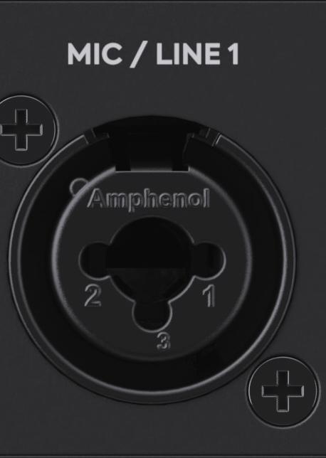
Mic/Line Inputs
Four Audient Console Mic Preamps are provided on combi-jack inputs. Their gain and related settings can be controlled from the hardware or from iD Control.
Instrument and Headphone Connections
The two JFET instrument inputs and two headphone outputs are located on the front edge of iD4+.

Typical Connection Examples
Recording a Microphone or Instrument
Connect a microphone to the required rear Mic/Line input (1–4), or a guitar or bass to either front JFET instrument socket. The front JFET sockets take over Inputs 1 and 2 respectively when connected. Select the corresponding input in your DAW and set Input Gain while watching the recording meter. Enable +48 V only if the microphone or connected equipment requires phantom power; check its instructions first.
Connecting Speakers and Headphones
Connect your speakers to the MAIN outputs, and a second pair to ALT if required. HP1 and HP2 are independent headphone paths, each with its own output level and source selection in the Monitor Reference Window. Choose the intended listening mix for each output and raise the level gradually.
Computer and USB Power Connections
Connect the USB-C COMPUTER port for data and bus power. ALT POWER provides supplementary power only and cannot be used as a USB audio connection. The rear panel also includes two optical inputs, two optical outputs and a BNC word-clock output.
Using External Equipment with Hardware Inserts
For an external compressor or processor, connect the channel's INSERT SEND to the processor's input and connect the processor's output to the matching INSERT RETURN. The Send is taken after the interface's preamp; the Return reconnects to the analogue input path ahead of the converter. This lets you use an external processor, such as a compressor on a vocal input, as part of the recording signal chain. Match the channel's Send and Return, set the level at the external processor while watching the input meter, and make a short test recording to check for clipping before recording a full take.