Hardware Controls & Monitoring
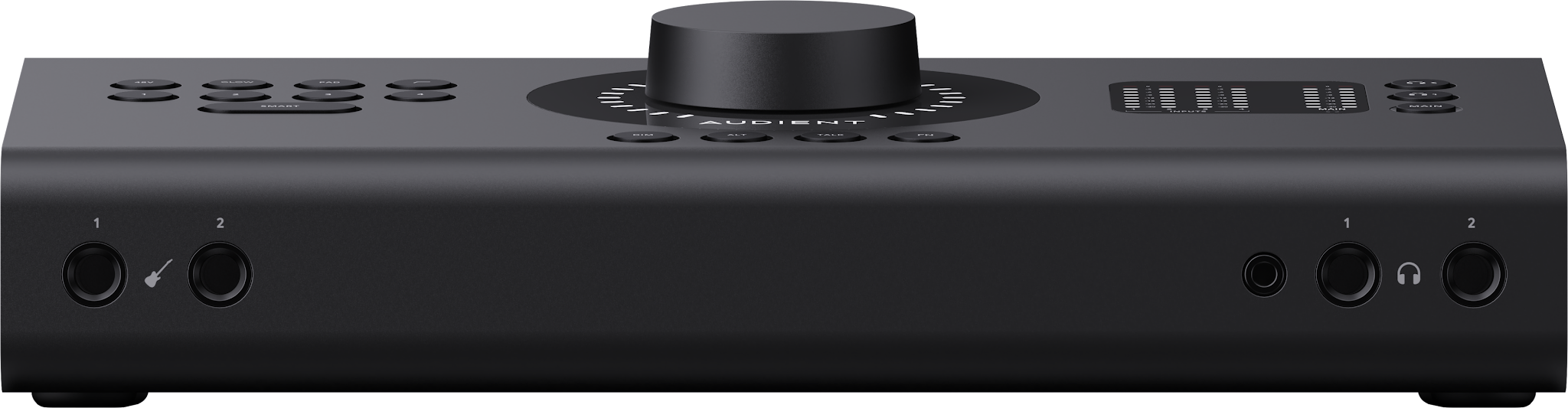
Monitoring
Output Mode
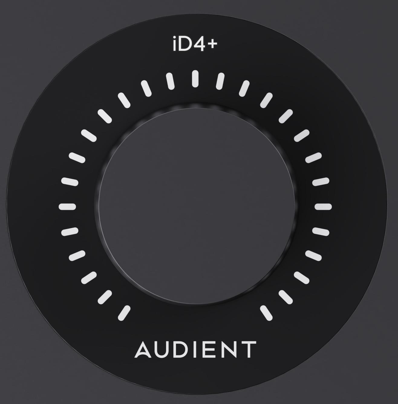
After startup, iD4+ enters Output Mode with the MAIN button illuminated. In this mode, the Control Wheel adjusts the level of the output currently in focus.
Turn the Control Wheel clockwise to increase the level or anti-clockwise to decrease it. The LED ring follows the current setting and the corresponding level is also shown in iD Control. If the hardware is currently in Input Mode, changing the monitor Output Volume in iD Control temporarily displays the adjusted monitor level on the Control Wheel LED ring.
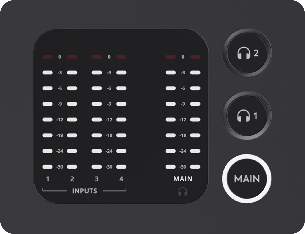
In Output Mode, the hardware meter ladder displays output metering. It is a fixed ladder of illuminated segments and does not change scale. The source being metered is indicated by the illuminated legend beneath the ladder.
Global Mute
Tap the Control Wheel to engage Global Mute, and tap it again to restore the muted outputs. This is separate from pressing and holding an individual output button to mute only that output. In iD Control, the Global Mute scope can be configured for the speaker outputs or all outputs.
Main and ALT Monitor Outputs
Main and ALT allow switching between two connected pairs of studio monitors without changing cables. Outputs 1–2 are used for the Main monitor output and Outputs 3–4 are used for the ALT monitor output.
MAIN is selected by default. Press ALT to switch monitoring to Outputs 3–4. The ALT button illuminates and iD Control reflects the change. Press MAIN to return monitoring to Outputs 1–2.


RoomTune Monitor Correction can be used with both the Main and ALT monitor outputs.
Muting the Active Monitor Output
Press and hold the active monitor-output button for one second to mute that output. The selected button pulses while muted and the state is also shown in iD Control.
When MAIN is active, hold MAIN to mute the Main speaker output. When ALT is active, hold ALT to mute the ALT speaker output.
Repeat the same action to restore the selected output.
DIM
DIM temporarily reduces the active Monitor Output without changing its normal listening level. The amount of reduction is set in iD Control.
Press DIM to engage the reduction. The DIM button illuminates and the Monitor Output level is reduced. Press DIM again to return to the previous monitor level.
Dim Amount can be set from -12 dB to 0 dB and defaults to -10 dB. The Control Wheel LED ring remains at the original monitor-level indication while DIM is active.

Talkback
Talkback sends the selected input to the headphone mix for communication from the control position. iD4+ has a dedicated TALK button.
Talkback is a latching control. Press TALK once to enable it and again to disable it. The hardware button and Talkback state in iD Control stay in sync.
The Talkback source is configured in iD Control and uses one of the iD4+ input channels.
When Talkback is enabled, the talkback signal is sent to the headphone monitoring path and the monitor output is dimmed.

Function Button
The FN button provides hardware access to assignable monitoring functions. The hardware and software FN controls are linked, so changes made from either location are reflected in the other. Configure the assignment in the Function Button settings in iD Control, or using the FN control in the Monitor Panel. The selection is stored in the interface for Standalone Mode, allowing the hardware to use its saved assignment when iD Control is not actively controlling it.

The FN button can be assigned to monitoring functions in iD Control.
The currently selected FN assignment is shown in the iD Control Monitor Panel.
Mono and M/S Mode
Use MONO to audition the mix without stereo separation. The Mono Mode setting in iD Control determines whether this uses the Left channel, the Centre sum of Left and Right, or the Right channel. The default Mono Mode is Left.

M/S Mode is a more advanced monitoring check that removes centre information using polarity inversion. It sums the signal to mono as part of this process. When M/S Mode is active, Mono is also shown as active.

Both Mono and M/S Mode can be controlled from iD Control and can be assigned to the FN button.
Headphone Monitoring
iD4+ provides two independent headphone outputs, HP1 and HP2, so two listeners can have different headphone levels and, when needed, different mixes. Each output has its own level and source selection.
Press headphone button 1 or 2 to place that headphone output in focus. The selected headphone button illuminates, MAIN illumination clears and the Control Wheel LED ring redraws to show the selected headphone level.
Turn the Control Wheel clockwise to increase the selected headphone level or anti-clockwise to decrease it. Changes made from iD Control are reflected by the hardware while that headphone output remains in focus.
Each headphone level can be adjusted from -128 dB to 0 dB in iD Control.
Press and hold a headphone button for one second to mute that headphone output. The selected button pulses while muted. Press and hold again to restore it.

Inputs and Recording
Analogue Inputs
iD4+ provides four Audient Console Mic Preamps with combi-jack inputs.
Two dedicated JFET instrument inputs are available for guitar and bass. When connected, the JFET inputs take precedence over Mic/Line Inputs 1 and 2 respectively.
Select an analogue input to enter Input Mode. The selected input button illuminates and the Control Wheel adjusts that channel's input gain. Press MAIN to return to speaker Output Mode, or select a headphone output to adjust its level.
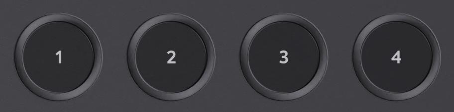
Turn the Control Wheel clockwise to increase the gain or anti-clockwise to reduce it. The LED ring follows the current gain setting and the corresponding gain control in iD Control updates at the same time.
Input Metering
iD4+ provides hardware input metering for the four Mic/Line input channels. Incoming input levels are displayed on the hardware input-meter ladder and on the corresponding iD Control channels.
Muting an Input
Press and hold the selected input-channel button to mute it. The input button pulses while the channel is muted. Press and hold the button again to restore the channel.
+48 V Phantom Power
Some microphones need +48 V phantom power to operate. If your microphone requires it, iD4+ can provide +48 V from the Mic/Line inputs. If you are unsure, check the microphone manufacturer's instructions before enabling phantom power.
Select the required Mic/Line input and press +48 V. The +48 V button illuminates red and the state is also shown on the corresponding channel in iD Control. If focus moves to an input where +48 V is not enabled, the hardware +48 V illumination clears; returning to a channel with +48 V enabled restores the illuminated state.

Press +48 V again to disable phantom power.
+48 V is disabled by default and is available on the rear Mic/Line inputs. When the JFET instrument sockets take over Inputs 1 and 2, phantom power is unavailable on the corresponding instrument paths.
If you attempt to enable +48 V on an input currently using its JFET instrument socket, the +48 V button flashes red twice and phantom power remains disabled.
GLOW and the Analogue Tone Suite
Press GLOW to enable HMX MOSFET Harmonic Saturation and LIFT High-Frequency Lift together on the selected input channel.

The GLOW button illuminates while both processes are active, and their status is also shown in the corresponding channel in iD Control.
GLOW follows the currently focused channel. Selecting a channel where GLOW is off clears the hardware illumination; returning to a channel where GLOW is enabled restores it. If HMX and LIFT are both enabled individually in iD Control, GLOW also becomes active automatically.
If either HMX or LIFT is disabled separately in software, GLOW is no longer active while the remaining process stays enabled.
PAD
iD4+ provides a fixed -10 dB PAD on the analogue input channels. Use it when a high-level source, such as a close-miked drum or a strong line-level output, needs attenuation to maintain a clean recording level. Check the input meter when switching PAD on or off.
PAD reduces the incoming signal level without changing the stored Input Gain setting. The control operates per channel, so engaging PAD on one channel does not affect the others unless channels are stereo paired.
Select the required input and press PAD to engage it. The PAD button illuminates and the channel state is reflected in iD Control. Press PAD again to disable it.
When PAD is engaged, the input level falls by 10 dB on the hardware and software input meters; disabling PAD restores the level by the same amount.

High-Pass Filter
iD4+ provides a high-pass filter control for the selected input channel.
The HPF can be switched on and off from the hardware, with the state reflected in iD Control.

Standalone Mode:
iD4+ can operate without a host computer connected. To prepare a standalone configuration, connect iD4+ to a computer running iD Control, set up the required routing and monitoring, then choose File > Save Standalone State.
This saves the device's internal audio routing, cue mixes and levels, FN button assignment and input DSP settings to its internal memory. The saved state is recalled when iD4+ is powered without iD Control, either from ALT POWER or when connected to a computer without iD Control installed.
For standalone operation without a computer, connect a 5 V / 3 A (15 W) USB-C power supply to ALT POWER using a USB-C to USB-C cable. ALT POWER supplies power only, not audio or control data.
Changes made in iD Control after saving do not automatically overwrite the stored standalone state. To use those changes in Standalone Mode, choose File > Save Standalone State again.
To reset the saved standalone configuration, choose File > Reset Standalone State in iD Control. This returns the standalone state to its factory defaults.