Digital I/O & Clocking
Optical Digital Inputs and Outputs
The two iD4+ optical inputs and outputs connect ADAT or S/PDIF equipment.
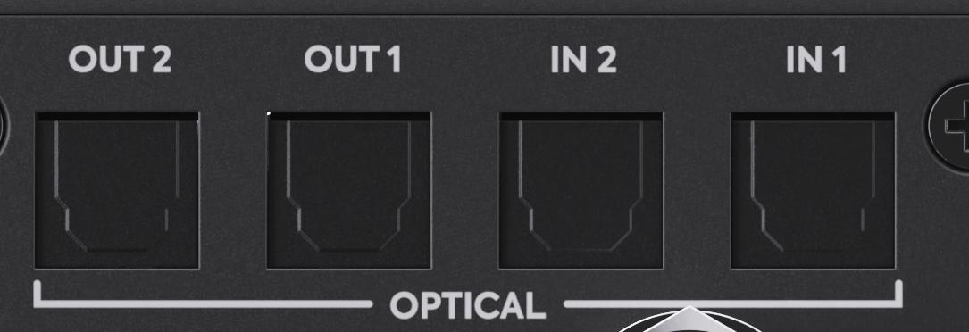
Set each optical port to the format required by the connected equipment. In ADAT mode, iD4+ can provide up to 16 channels of digital input and 16 channels of digital output in total, depending on sample rate.
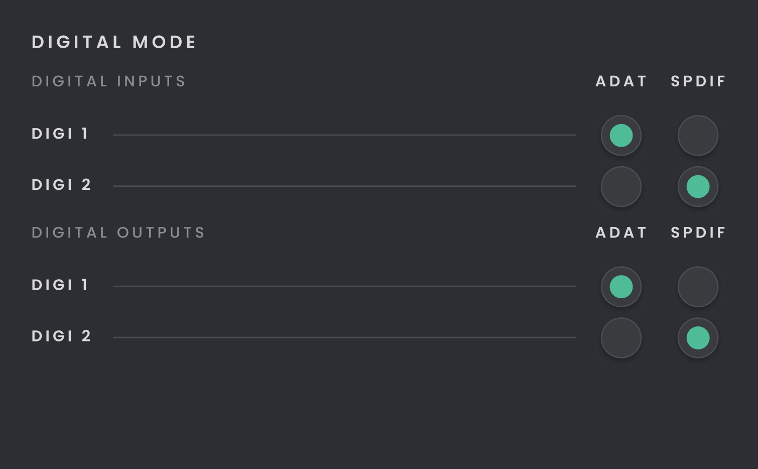
Input and output modes are independent, so the optical inputs and outputs do not have to use the same digital format.
S/PDIF provides two digital channels per optical port.
Word Clock Output
The BNC word clock output sends a clock signal from iD4+ to external ADAT equipment.
The BNC word clock connection is output-only.
System Status
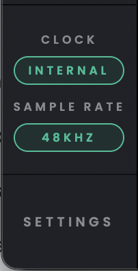
Check the System Status area in iD Control to see the current sample rate and clock source. Double-click either status pill to open Settings.
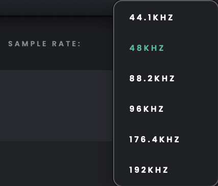
Available sample rates are 44.1, 48, 88.2, 96, 176.4 and 192 kHz. To change the sample rate, open the Sample Rate dropdown in the top-right navigation bar of iD Control.
Above 96 kHz, EQ, Compressor and Comfort Reverb are unavailable.
Digital Mode
Set the optical inputs and outputs independently to match the connected equipment. Choose ADAT for ADAT signals or S/PDIF for two-channel optical S/PDIF.
ADAT is selected by default for digital input operation.
In ADAT mode, the available channel count per optical port changes with sample rate:
44.1/48 kHz: 8 channels
88.2/96 kHz: 4 channels
176.4/192 kHz: 2 channels
At higher sample rates, only the first four or first two ADAT channels on each optical port remain available, respectively.
S/PDIF mode provides two digital channels per optical port. Optical S/PDIF is not supported at sample rates of 96 kHz or above.
Clock Source
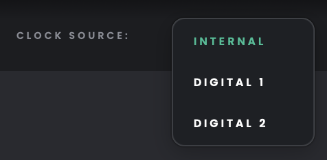
Use Internal for normal operation, or select Digital 1 or Digital 2 when you want iD4+ to clock from the corresponding optical input.
Internal uses iD4+’s own clock. Digital 1 and Digital 2 use the clock carried by their corresponding optical inputs.
Internal is the default clock source. The BNC word clock connection is output-only and is not a selectable iD4+ clock source.
Connecting an External ADAT Microphone Preamp
Use a TOSLINK optical cable to connect the external preamp's ADAT OUT to iD4+'s optical input. In iD Control, set the input's Digital Mode to ADAT and match the sample rate on both devices. Select the required digital input in your DAW. The available ADAT channel count at each sample rate is shown in the Digital Mode table above.
Choosing the Digital Clock Source
There must be one clock master in a digital setup. If the external ADAT preamp is the master, set it to its internal clock and select the appropriate Digital clock source on iD4+ so the interface synchronises to the incoming optical signal. Alternatively, if iD4+ is the master, select Internal as its clock source and arrange for the external preamp to follow the iD4+'s optical digital output or BNC word-clock output, using a connection and clocking mode supported by that preamp. Always match the sample rate across connected devices.
If the Digital Inputs Produce Clicks or No Audio
Check that the optical cable runs from the source's output to the interface's input, the Digital Mode matches the source format, and both devices agree on the clock master and sample rate. A digital signal can be connected but still unusable if the devices are not synchronised. If the digital input is missing in the DAW, check whether the selected sample rate reduces the number of available ADAT channels.